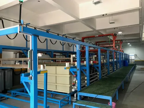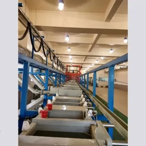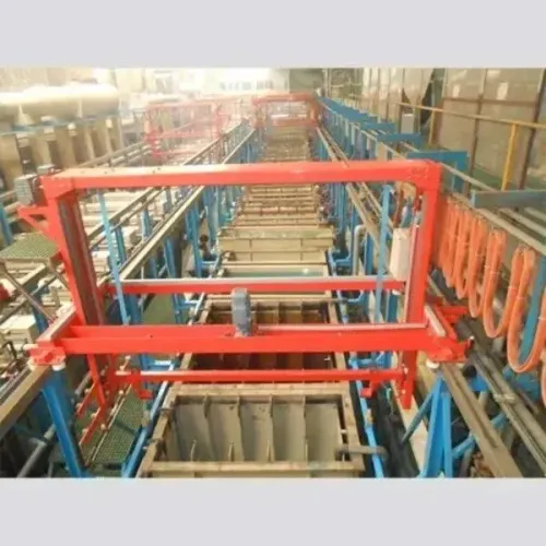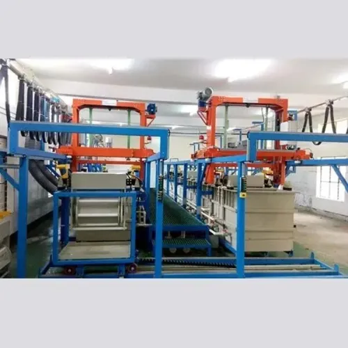
A reliable aluminium anodising line depends on more than an acid tank: the alloy, pretreatment, electrical load, cooling, rinsing and sealing sequence determine the finished surface. By the end, you will be able to match an anodising process and coating specification to the part, identify the plant controls that protect consistency, and compare the design issues that affect operating cost and compliance.
Key takeaways
- Match oxide thickness and finish to the part’s wear, corrosion and appearance requirements.
- Control current density, bath temperature and chemistry together, not as isolated settings.
- Use staged rinsing and sealing to protect colour, corrosion resistance and surface quality.
- Record recipes, bath tests, rack layouts and batch results for traceable production.
How aluminium anodising builds the oxide layer
The oxide layer grows out of the aluminium itself; it is not a separate metal film placed on top. That makes aluminium anodising an electrochemical conversion coating: the part becomes the anode, and controlled electrical current converts its surface into porous aluminium oxide.
1. Load and rack the part with firm electrical contact. The contact point will remain uncoated, while poor contact creates thin areas or heating. Allow for oxide growth in the dimensional design of bores, threads and mating surfaces.
2. Clean the surface with alkaline cleaning to remove oil and handling residue. Follow with etching and desmutting to remove the natural oxide, embedded soils and alloying-element residues. Inadequate preparation leaves stains, pits or uneven colour.
3. Transfer the prepared part through rinses into the anodising bath. Current drives oxygen-containing ions into the aluminium surface, building the oxide inward and outward rather than depositing a layer from the electrolyte. Bath temperature, free acid, dissolved aluminium, current density, agitation and time determine the result together.
4. Rinse thoroughly after anodising so acid and dissolved metals do not contaminate the next tank. Seal the pores with the specified hot-water, nickel-salt or other sealing process; anodising alone does not provide a fully sealed surface.
5. Rinse again, remove trapped water from holes and profiles, and dry with controlled air or heat. Inspect contact marks, colour, handling damage and dimensions before packing.
Choose the process, thickness and finish for the part
A part needing colour and general corrosion protection usually suits sulphuric acid anodising; sliding, abrasive or high-wear parts need hard anodising. Specify the coating before designing fits: roughly half the stated oxide thickness adds to each coated surface, while the remainder grows into the aluminium. A tight bore can seize after treatment.
| Process | Coating choice | Best fit |
|---|---|---|
| Sulphuric acid anodising | 8–20 µm for general protection and colour | Decorative parts, housings and moderate-duty components |
| Hard anodising | About 25–50 µm, with drawing tolerances for growth | Wear faces, cylinders, guides and parts exposed to abrasion |
| Architectural anodising | Commonly 15–25 µm, with colour and appearance limits | Exposed façades, frames and visible building components |
Do not specify a colour without naming the alloy, temper and pretreatment. Etching, bright dipping and chemical polishing change texture before anodising; extrusion lines, weld zones and alloying elements can remain visible. An architectural anodising finish therefore needs an approved sample, viewing conditions and an acceptable shade range, not only a colour name.
Choose decorative anodising thickness for appearance and corrosion duty, then state the alloy and minimum local thickness on the drawing. Sealing closes pores and affects dye bleed, corrosion resistance and acid-test results. Select hot-water or nickel-salt sealing as part of the specification because each changes chemistry control, wastewater and colour retention.
Check thickness at representative high- and low-current locations with an eddy-current method covered by ISO 2360. Do not accept bath appearance as proof of coating performance.
Design the line around current, heat and chemical balance
An undersized rectifier can leave a full tank below the required coating rate even when the tank volume is adequate. Calculate anodising rectifier capacity from the load’s active surface area and specified current density, then add allowances for rack contact losses and production utilisation. Size busbars, hooks and contacts for the same current.
| Control | Decorative or protective sulphuric anodising | Hard anodising | Failure if mis-sized |
|---|---|---|---|
| Electrical control | Stable current density and controlled ramp | Higher coating-build demand with tighter regulation | Thin areas, burning or uneven thickness |
| Thermal control | Cooling sized for the worst batch | Strong cooling, agitation and heat removal | Temperature drift and colour variation |
| Rack and contact | Firm, repeatable contact with acceptable marks | High-capacity contacts that resist heating | Arcing, contact burns or intermittent rejects |
Bath temperature control must remove heat from the electrical load and circulation through a heat exchanger or equivalent system. Do not size cooling for the average batch; a high-area load can push the bath outside its process window.
Control free acid, dissolved aluminium, contaminants, agitation and exposure time together. Restoring acid concentration will not necessarily restore the same coating response after dissolved aluminium has risen.
Specify interlocks that stop rectifier output when tank level, circulation, cooling, exhaust or rack position is unsafe. Recipe automation should record current density, temperature, dwell time, ramping, transfer delays and load identity; otherwise an incorrect alloy or rack orientation can produce a convincing but nonconforming batch.
Control rinsing, sealing and finished-part quality
Give each rack adequate drain time between tanks, then use controlled spray or immersion rinses to remove acid, caustic, dye and sealant. Counter-current rinsing keeps cleaner water at the final rinse and limits carry-over into anodising and sealing tanks. Track rinse conductivity and set a replacement limit; adding more tanks alone does not control contamination.
Anodising sealing is a separate performance step, not an automatic result of forming the oxide. Put the selected hot-water or nickel-salt sealing method, temperature, time and chemistry limits in the recipe. Poor control leaves dye bleed, weak acid resistance and reduced corrosion protection.
Anodising quality control must combine process records with tests on representative parts. Record bath conditions, load, current and treatment time, then inspect locations that reflect current-density differences on long, recessed or densely racked components.
- Thickness: Use ISO 2360 thickness measurement at defined locations, including edges and recessed areas where the specification permits.
- Sealing: Check with the specified dye-bleed or acid-resistance test; bath appearance cannot prove adequate sealing.
- Corrosion: Run the acceptance test named on the drawing or purchase specification, using panels or parts from the production load.
- Appearance: Inspect colour, stains, burning, contact marks and shade variation under agreed lighting and viewing distance.
Keep rack contacts clean and tight. A growing oxide film at a poor contact raises resistance, causing local heating, thin coating, arcing or rejects. Record failed locations so the rack design and contact points can be corrected.
Turn the process recipe into a safe, traceable plant
Specify the plant from the worst-case load and chemistry, not tank volume. Require the supplier to convert your approved recipe, peak and upset flows, ventilation hazards and traceability needs into a documented design basis.
1. Size the rectifier from active surface area multiplied by the specified current density, with allowances for rack contact loss and realistic production utilisation. Check busbars, contacts, cooling and ramp control; a full tank cannot compensate for an undersized power circuit.
2. Require anodising plant automation to interlock rectifier output with tank level, circulation, cooling, exhaust and rack position. Recipe control must record load ID, alloy, rack orientation, dwell times, transfer delays, current profile and rinse results so a plausible-looking but incorrect batch is not released.
3. Demand separate chemical ventilation and containment for acid, caustic, oxidising and solvent-containing stages. The supplier must justify duct and scrubber materials against chemistry, temperature and aerosol load; weak extraction exposes workers, while excessive unbalanced airflow increases evaporation and energy use.
4. Design metal-finishing wastewater treatment for normal rinses, drag-out, tank dumps and concentrated maintenance solutions. Identify fluoride, dyes, nickel sealants and aluminium sludge before selecting treatment and sludge disposal equipment, then compare the discharge design with 40 CFR Part 433 and your local permit.
5. Put the sealing method, chemistry limits and acceptance tests into the purchase specification. Require dye-bleed, acid-resistance and corrosion checks where relevant, plus drawings, spare-parts lists, training and commissioning records.
AK Automation Systems can help coordinate plant interfaces, but make the supplier prove capacity and safeguards through documented factory and site acceptance tests.
Frequently asked questions
How does aluminium anodising build the oxide layer?
The aluminium part becomes the anode in an electrolytic cell, and controlled current converts its surface into porous aluminium oxide.
How do you choose anodising thickness and finish?
Select thickness and finish from the part’s exposure, wear, dimensional limits, colour requirement and appearance standard.
What must an anodising plant control during processing?
Control current density, bath temperature, chemical concentration, agitation and loading so the oxide layer develops consistently.
Why are rinsing and sealing important after anodising?
Rinsing removes process chemicals, while sealing closes pores in the oxide layer to improve corrosion resistance and finished-part performance.